

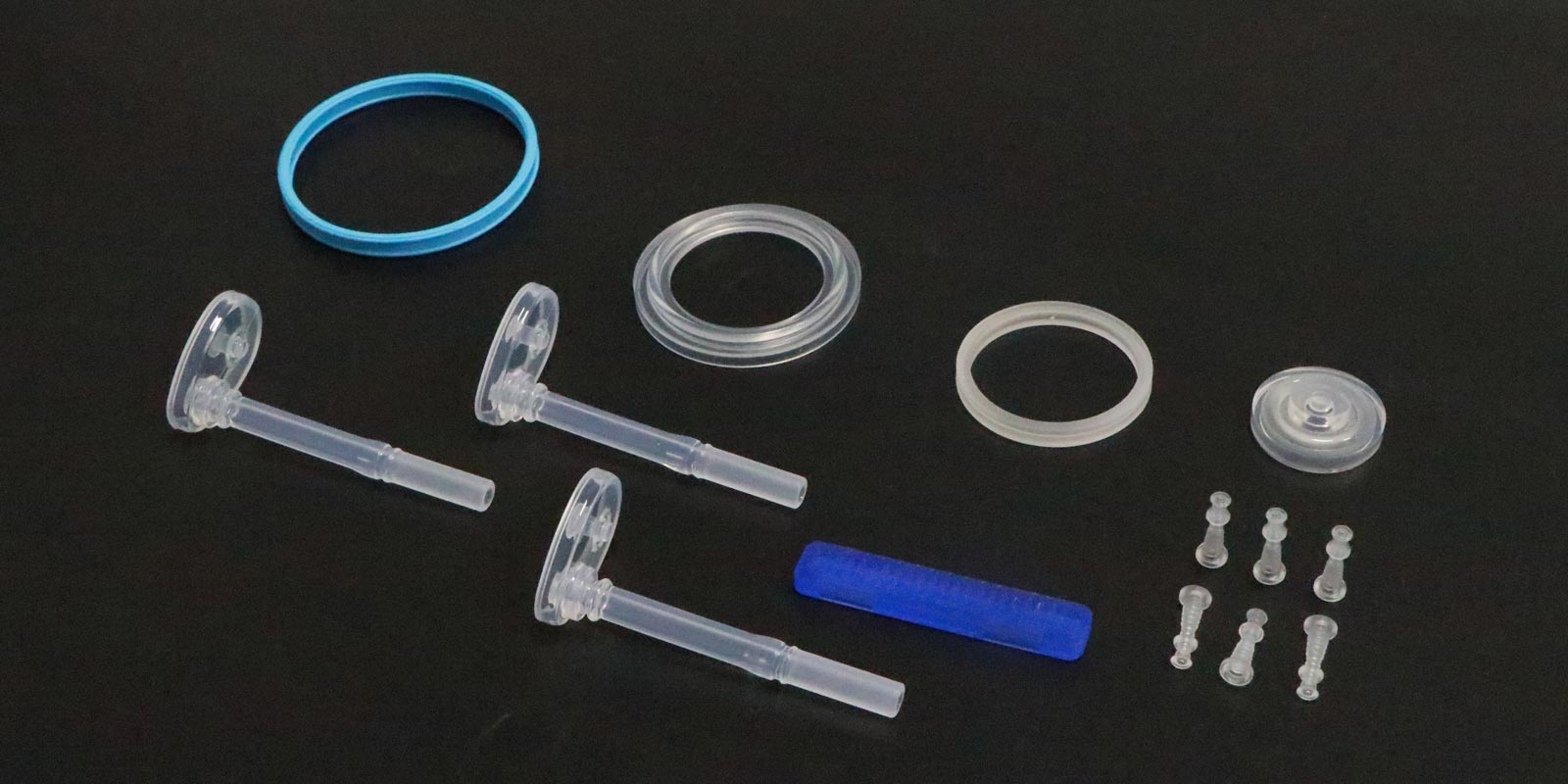
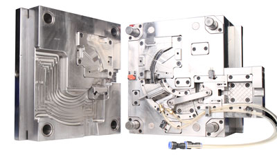
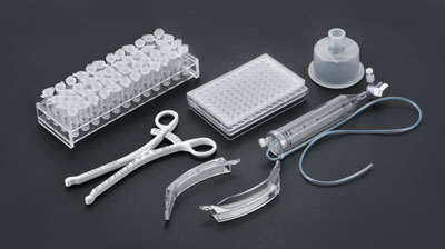



Medical injection molded parts are directly related to patient safety. Even the slightest defect can lead to serious consequences. From flash to sink marks, from gas lines to cracking, every defect has clear causes and corresponding solutions. This article systematically reviews the most frequent defects in medical injection molding production and provides targeted countermeasures from three dimensions: mold, process, and material.
Description: Excess thin plastic sheets appear on the edges, parting lines, or slider joints of molded parts. For example, flash on the edge of a syringe barrel not only affects appearance but may also generate plastic debris during medical operations, causing safety accidents.
Causes: Insufficient mold clamping precision and worn parting surfaces are the primary causes. Excessively high injection pressure, injection speed, or holding pressure can also cause melt to overflow from gaps.
Solutions:
At the mold level, correct the clamping surface, re-lap the parting surface, and ensure sufficient clamping force. At the process level, reduce injection pressure and speed, and appropriately shorten holding time. For micro medical parts, insufficient clamping force is the number one cause of flash. Always verify that the injection molding machine tonnage matches the requirement.
Description: Localized surface depressions appear on molded parts, mostly in areas with large wall thickness changes, ribs, or the back side of bosses. For instance, sink marks on the drip chamber of an IV set reduce transparency and weaken structural strength.
Causes: Uneven cooling and shrinkage of plastic is the root cause. Thick-walled sections cool slowly and shrink more, pulling thin-walled sections inward to form depressions. Insufficient holding pressure or holding time during the holding phase, which fails to effectively compensate for shrinkage volume, is the direct trigger.
Solutions:
At the process level, extend holding time and increase holding pressure to ensure melt continuously fills shrinkage areas. At the mold level, optimize the cooling system with evenly distributed cooling water channels, and add cooling inserts at thick-walled areas to accelerate cooling. At the structural design level, add transition fillets at abrupt wall thickness changes to avoid excessive wall thickness differences.
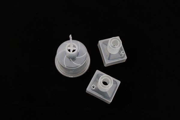
Description: When two or more melt flow fronts meet without fully fusing, a line-shaped mark forms on the surface. On appearance-critical parts such as hemodialyzer housings, weld lines not only affect aesthetics but may also become breeding grounds for bacteria.
Causes: Unreasonable gate location, quantity, or shape leads to non-uniform cavity filling. Excessively low melt temperature or injection speed worsens melt flowability, making weld lines more prominent.
Solutions:
Optimize gate design to achieve uniform cavity filling. Use multi-stage injection: medium speed to fill the runner, slow speed to fill the gate, fast injection, then low-pressure slow fill to allow gas to vent at each stage. At the same time, appropriately increase material temperature and mold temperature to improve melt flowability.
Description: The part surface shows wave-like or cloud-like patterns (gas lines) or silver thread-like streaks (silver streaks). These are especially obvious on transparent parts such as blood collection tubes and medical catheters, directly affecting medical staff's ability to observe internal liquids.
Causes: Raw material moisture content exceeds the standard, causing water to vaporize into gas at high temperatures. The mold venting system is poorly designed, with vents blocked or insufficient in number. Excessively high injection speed causes melt to entrap air that cannot escape in time.
Solutions:
Raw materials must strictly follow drying procedures. Set drying temperature and time according to material characteristics to ensure moisture content meets standards. At the mold level, improve the venting system, clean vent slots regularly, add vent slots at melt flow endpoints and parting lines where gas tends to accumulate, and use vacuum venting devices when necessary. At the process level, reduce injection speed and adopt multi-stage injection.
Description: The molded part undergoes overall or local shape distortion and no longer meets design requirements. Large or thin-walled components such as medical petri dishes, when warped, affect placement stability and internal liquid distribution.
Causes: Uneven cooling across different sections is the core cause. When wall thickness distribution is uneven or the cooling system is poorly designed, different areas shrink at different rates, inevitably leading to deformation. Improper demolding methods or unreasonable ejector pin placement also worsen deformation.
Solutions:
At the mold level, optimize the cooling system to ensure consistent temperature across all areas. Correct ejector pin distribution and install tensioning mechanisms such as sprue pullers. At the process level, extend cooling time to ensure the product is fully solidified before demolding. At the structural design level, keep wall thickness as uniform as possible to reduce cooling differences.
Description: The actual dimensions of the molded part do not match the design dimensions, either oversized or undersized. For example, dimensional deviation in precision insulin syringe components can directly cause assembly difficulties or even functional failure.
Causes: Insufficient mold manufacturing precision is the key factor. Positioning errors and tool wear on CNC machining centers both lead to cavity dimension deviations. Shrinkage rates vary between material batches, and fluctuations in process parameters such as injection temperature, pressure, and cooling time also affect dimensional accuracy. Excessively high barrel temperature reduces melt viscosity, increases cooling shrinkage, and makes product dimensions smaller.
Solutions:
At the mold level, use ultra-precision five-axis CNC machining centers, control critical dimension tolerances within plus or minus 0.005 mm, and regularly maintain and calibrate equipment. At the material level, select stable suppliers, strictly inspect shrinkage rates and other key indicators for every incoming batch, and adjust process parameters after trial runs. At the process level, use advanced injection molding machine control systems to monitor and adjust parameters in real time to ensure full-process stability.
Description: Molded parts are prone to fracture and breakage during use, failing to meet mechanical performance requirements. For example, insufficient strength in an IV tube clamp prevents it from properly gripping the tube. Cracking mostly concentrates at corners, snap fits, or abrupt wall thickness changes.
Causes: The material itself lacks adequate strength or toughness. Defects such as sink marks and air bubbles reduce the effective load-bearing cross-section. Excessively high injection pressure or holding pressure creates excessive internal residual stress, which releases during demolding and causes cracking. Insufficient demolding draft or uneven ejector pin distribution causes demolding stress cracks.
Solutions:
For material selection, orthopedic implants can use glass fiber reinforced polyamide with tensile strength exceeding 150 MPa while maintaining good toughness. At the process level, reasonably reduce injection pressure and holding pressure, and extend cooling time. At the mold level, optimize demolding structure, increase demolding angle, distribute ejector pins reasonably, and add stress relief grooves at crack-prone areas.
Description: Small features and corners of the finished part fail to fill completely.
Causes: Insufficient injection pressure or speed, material temperature too low, mold runner or gate too small, or poor venting preventing melt from reaching distant areas.
Solutions:
Increase injection pressure and speed, raise material temperature and mold temperature. Enlarge gate size and thicken runners. Optimize the venting system to ensure gas inside the cavity vents smoothly. For crystalline plastics such as nylon and polypropylene, set higher material temperatures.
This is not an appearance defect, but it is the most fatal hidden danger in medical injection molding. Mold surface oil, bacteria, or dust adhering to the molded part surface can cause infection if it enters the human body. Unpolymerized monomers and additives in the material may produce biological toxicity.
Solutions:
Select materials that comply with ISO 10993 standards. For products in direct contact with blood or tissue, prioritize materials with excellent biological inertness such as PEEK and ultra-high molecular weight polyethylene. Establish clean rooms at Class 10,000 or higher cleanliness levels. Sterilize molds with high-temperature high-pressure steam or ethylene oxide before each injection molding run. Use medical-grade release agents.
Description: Molded parts deteriorate, swell, or release harmful substances after contact with chemicals such as drugs or disinfectants. For example, plastic medicine bottles may undergo chemical reactions when holding certain drugs, affecting drug safety.
Solutions:
Thoroughly evaluate the chemical resistance of the material to all substances it may encounter in the medical environment. Select appropriate materials based on the contact medium. For example, PPSU has excellent chemical resistance and is suitable for repeated high-temperature steam sterilization.
Q: What certifications are required for medical injection molding production?
A: Medical injection molding must comply with ISO 13485 Medical Device Quality Management System. Products exported to the United States must also meet FDA requirements. Before mass production, IQ (Installation Qualification), OQ (Operational Qualification), and PQ (Performance Qualification) must be completed. When conditions permit, produce three small batches of each part to form complete SOP documents.
Q: How can injection molding defects be fundamentally reduced?
A: Defect prevention is a full-process engineering effort. At the mold end, ensure machining precision and unobstructed venting. At the process end, determine optimal parameters through experiments and simulation and monitor them in real time. At the material end, strictly inspect incoming materials and perform proper drying. At the environment end, maintain clean room standards. All three are indispensable.
Q: What are the process differences between micro medical injection molding and standard injection molding?
A: Micro injection molding requires a screw diameter in the range of 12 to 18 mm with a reasonable L/D ratio to avoid material degradation. It uses high-speed high-pressure filling, with material temperature set as high as allowed and mold temperature also maximized. An image monitoring system must be equipped to prevent mold crushing. However, micro injection molding has the drawback of large runner volume, significant material waste, and longer production cycles.
Q: Are flash and burr the same defect?
A: Yes, they are different names for the same defect. Both refer to excess plastic sheets overflowing at parting lines or mating surfaces. The core countermeasures are identical: improve clamping precision, reduce injection pressure, and optimize the mold parting surface.
PREV:Why Do Medical Injection-Molded Parts Keep Failing? A Comprehensive Guide
NEXT:Medical Injection Molded Product Surface Scratches: Mold Issue or Demolding Method Issue?
Add: 62 Jinghai East Road, Chang'an Town, Dongguan City, Guangdong Province
Whatsapp: +86 13342659272
Email: Yuliya.chen@yizemould.com

Add: 62 Jinghai East Road, Chang'an Town, Dongguan City, Guangdong Province
Whatsapp: +86 13342659272
Email: Yuliya.chen@yizemould.com
 Home
Home