


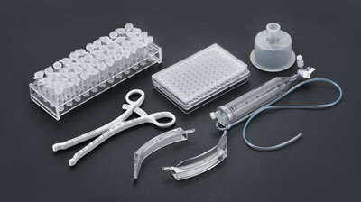


Medical injection molded parts have extremely stringent requirements for dimensional accuracy and surface quality. Flow marks, as one of the most common surface defects, not only affect product aesthetics but may also become hidden risks for cleanliness and quality audits. The essence of flow marks is the external manifestation of unstable melt flow within the cavity. To fundamentally resolve this issue, the melt flow condition must be systematically improved from three major dimensions: process parameters, mold structure, and material formulation.
Different forms of flow marks correspond to entirely different flow instability mechanisms. The right diagnosis leads to the right cure.
Concentric Ring Flow Marks — Diffusing outward from the gate in concentric circles. This occurs when low-temperature, high-viscosity melt is injected into the cavity in a semi-solidified, fluctuating state from the gate and runner, and is subsequently squeezed by follow-up melt, creating backflow and stagnant flow. Commonly seen in PC, POM, and other crystalline or high-viscosity materials.
Spiral Flow Marks — Caused by turbulent flow when melt transitions from a narrow runner cross-section into a larger cavity cross-section. Frequently appears on medical tubing and connectors with high length-to-thickness ratios and abrupt wall thickness changes.
Cloud-Like Flow Marks — When processing ABS or copolymer resins, excessively high processing temperatures cause volatile gases from the resin and lubricants to form cloud-like marks on the part surface. Especially common in medical-grade ABS and TPE materials.
Snake-Like Flow Marks and Radiation Lines — When the injection speed is too fast, the melt produces a jet effect or elastic fracture, forming snake-like patterns or radial lines on the surface. Commonly seen in thin-walled medical device housings.
Increase mold temperature and nozzle temperature. Mold temperature is the core variable affecting melt flow. For medical-grade PC materials, it is recommended to start from the supplier's recommended value and adjust in increments of 6 degrees Celsius each time, observing the results after 10 injection shots. Nozzle temperature should be at least 6 degrees Celsius higher than the previous setting to prevent excessive melt temperature drop as the melt passes through the nozzle. Barrel temperature should increase progressively from the rear zone, middle zone, front zone, to the nozzle zone, with each zone increasing by approximately 6 degrees Celsius, ensuring the melt reaches the gate in optimal flow condition.
Optimize the injection speed profile. Excessive injection speed is the main cause of snake-like flow marks and radiation lines, while too slow a speed leads to concentric ring flow marks. The best strategy is to use multi-stage injection: medium speed near the gate, high speed during the filling phase, and slow speed for hold pressure at the end. For medical tubing with high length-to-thickness ratios, a "slow-fast-slow" graded control can be used, allowing the melt to first enter the cavity smoothly, then accelerate to fill, and finally compress slowly.
Increase injection pressure and hold pressure time. When injection pressure and hold pressure are insufficient, the frozen layer cannot be firmly pressed against the mold surface, inevitably leaving flow-direction sink marks. Medical parts typically require high wall thickness uniformity. It is recommended to extend the hold pressure time until the part is fully cooled and set, with the shot-to-barrel material ratio controlled between 1:1.5 and 1:4.
Appropriately extend the molding cycle. A cycle time that is too short results in insufficient heating of the plastic in the barrel and a lower melt temperature. For medical-grade POM and other crystalline materials, sufficient plasticizing time must be guaranteed.

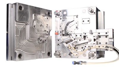
Optimizing the gating system is the top priority. The sprue should be designed with a large taper angle of 2 to 3 degrees, and the inner wall roughness Ra should not exceed 0.02 micrometers. The runner cross-section should prioritize a circular shape, with the diameter determined by the part weight and wall thickness — 6 to 10 millimeters for standard medical parts, and up to 12 to 16 millimeters for large thick-walled parts. A circular cross-section maximizes the reduction of flow resistance, far superior to rectangular or trapezoidal cross-sections. The gate should be placed at the thick-walled section, preferably using a tab gate, fan gate, or diaphragm gate. Gate depth should be equal to or slightly less than the cavity depth, so that the filling speed is reduced, creating an expansion flow rather than a jet.
Fine-tuning gate position and angle. Place the gate as close to the cavity wall as possible, maintaining a 4 to 5 degree angle between the gate and the moving mold. When the melt exits, it first encounters the cavity wall, which effectively prevents snake flow marks. For multi-gate layouts, the spacing should be controlled at 20 to 30 millimeters to ensure uniform filling.
Smooth transitions in cavity structure. The cavity inner wall needs fine polishing with a surface roughness Ra of 0.015 micrometers or less. Corners should have a fillet radius of no less than 3 millimeters to avoid sharp right angles that cause flow dead zones. Rib thickness should be controlled at one-third to one-half of the main wall thickness, with rounded roots.
The venting system cannot be overlooked. Vent channels should be prioritized at the melt flow end, cavity corners, and weld line areas. For general plastics, vent channel depth should be 0.01 to 0.02 millimeters and width 5 to 10 millimeters. For POM and other engineering plastics with poor flowability, vent channel depth can be increased to 0.02 to 0.03 millimeters. The parting line fit clearance should be controlled at 0.01 to 0.015 millimeters.
Proper placement of cold slug wells. Large cold slug wells must be set at the bottom of the gate and at the end of the runner, positioned at the end of the melt flow direction along the gate. The greater the influence of material temperature on flow performance, the larger the cold slug well must be.
For medical injection molded parts with high length-to-thickness ratios, materials with good flowability must be selected. The melt flow rate (MFR) should be recommended at 10 grams per 10 minutes or higher. Up to 1% molding lubricant can be added to improve flowability. For parts with even higher length-to-diameter ratios, the amount can be appropriately increased, but must be confirmed in consultation with the material supplier. For TPE medical soft-touch materials, linear SEBS-based materials should be prioritized, with appropriate oil filling and the addition of silicone-based lubricants, which can significantly improve flow performance.
Medical injection molded parts have strict requirements for cleanliness and traceability. The types and amounts of lubricants added to improve flow must undergo biocompatibility assessment. Release agents are only permitted in small quantities on threads and other areas where demolding is difficult. The mold surface can be considered for nitriding treatment, with a nitriding layer thickness of 0.05 to 0.1 millimeters, which improves wear resistance while reducing friction resistance, without affecting medical-grade cleanliness standards.
Eliminating flow marks is never achievable by adjusting a single parameter. It is a systematic engineering project. Seventy percent mold, thirty percent process — a reasonable gating system, adequate venting, and precise temperature control form the foundation. On top of that, through the fine coordination of temperature, pressure, speed, and time, the melt can fill the cavity smoothly and uniformly, eliminating flow marks at the root. Prevention is better than correction. It is recommended to introduce CAE mold flow analysis at the new product development stage to predict risks and optimize solutions in advance, eliminating flow marks at the mold design stage.
Q1: What is the fastest machine adjustment method for concentric ring flow marks on medical injection molded parts?
Prioritize increasing mold temperature and nozzle temperature, while also increasing injection speed and filling speed, and extending hold pressure time. If on-site conditions are limited, start by raising the nozzle temperature by at least 6 degrees Celsius, which usually delivers quick results.
Q2: For medical tubing with a very high length-to-thickness ratio, what mold modifications can reduce flow marks?
Enlarge the gate and runner cross-sections, prioritizing circular cross-sections for both the gate and runner. Install a heater at the gate to raise the local temperature. Set a large-sized cold slug well at the bottom of the gate. Place the gate at the thick-walled section and use a fan gate or diaphragm gate configuration.
Q3: TPE medical soft-touch injection molded parts have severe flow marks. How can this be improved at the material level?
Select linear SEBS or other low molecular weight base materials. Add an appropriate amount of plasticizer and silicone-based lubricant to reduce melt viscosity. Control the barrel temperature between 180 and 220 degrees Celsius. Appropriately increase screw speed to enhance shear plasticization, while avoiding material degradation.
Add: 62 Jinghai East Road, Chang'an Town, Dongguan City, Guangdong Province
Whatsapp: +86 13342659272
Email: Yuliya.chen@yizemould.com
Add: 62 Jinghai East Road, Chang'an Town, Dongguan City, Guangdong Province
Whatsapp: +86 13342659272
Email: Yuliya.chen@yizemould.com
 Home
Home