

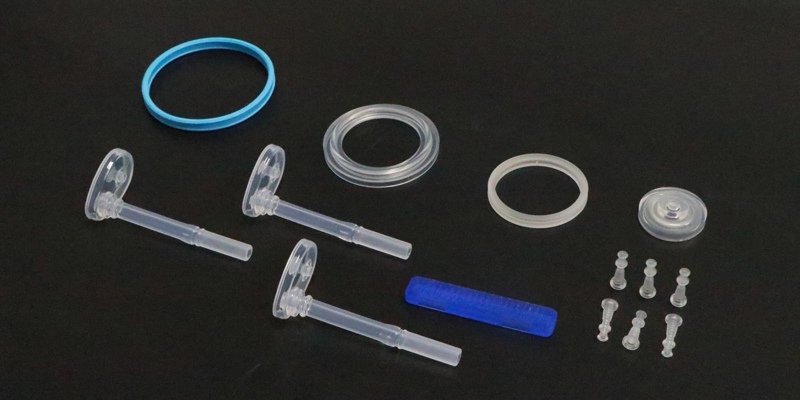

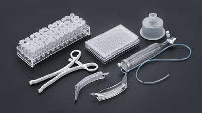


Medical injection-molded products, due to their direct contact with human tissues, blood, or body fluids, have extremely high requirements for dimensional accuracy, shape stability, and biocompatibility. However, defects in the design, manufacturing, and use of molds can lead to product deformation, thereby affecting the safety and effectiveness of medical procedures. This article analyzes the core issues in medical molds that may cause product deformation from four dimensions: mold structure, cooling system, material selection, and process matching.
1.1 Unreasonable Parting Surface and Ejection Mechanism Design
If the parting surface of a mold has sharp corners, undercuts, or excessive clearance, it can cause uneven lateral forces on the injection-molded part during ejection, leading to local stress concentration. For example, the mold for a certain type of infusion set drip chamber lacked an ejection draft angle on the parting surface, causing the product edges to be scratched by the mold core during ejection and forming 0.2mm micro-cracks. These cracks subsequently led to bending deformation due to stress release during use.
Additionally, improper design of the ejection mechanism (such as an insufficient number of ejector pins or misaligned positions) can result in uneven force distribution during ejection. The mold for a cardiac pacemaker housing used only two ejector pins, while the product had a wall thickness of 3mm. During ejection, the middle section of the housing sagged due to lack of support, causing a 0.5mm depression that directly affected its sealing performance.
1.2 Imbalanced Gate and Runner System
The position, number, and size of gates directly influence the melt flow path and filling pressure distribution. If the gate is designed in a thin-walled area of the product (such as the end of a catheter connector), the melt must travel a long distance to fill the cavity, causing the front end to cool and solidify while the rear end remains under pressure, ultimately leading to product warping. The mold for a PICC catheter used a single-gate design with a runner diameter of only φ2mm, resulting in a 30% pressure drop at the filling end. This caused the tail section of the product to twist by 0.3mm in an S-shape due to uneven shrinkage.
2.1 Cooling Channel Layout Defects
Medical products often have significant wall thickness variations (e.g., a blood collection tube with a wall thickness of 0.8mm vs. reinforcing ribs of 2.5mm). If the cooling channels are only arranged around the outer perimeter of the cavity, the thick-walled areas will cool 40% slower than the thin-walled areas, creating internal stress gradients. The mold for a blood collection tube lacked cooling channels beneath the reinforcing ribs, causing the rib area to shrink by 0.15mm more than the tube body during cooling. This resulted in the tube bending by 0.8° toward the ribs.
2.2 Insufficient Thermal Conductivity of Mold Materials
If the mold core/cavity is made of a material with low thermal conductivity (e.g., P20 steel with a thermal conductivity of 26W/m·K), compared to high-conductivity materials (e.g., H13 steel with 32W/m·K), the cooling efficiency is reduced by 23%. The mold for an orthopedic implant used P20 steel for the core, extending the cooling time of thick-walled areas by 8 seconds. This increased the shrinkage rate by 0.3% compared to the design value, creating a 0.2mm gap between the implant and bone contact surface and affecting initial stability.

3.1 Chemical Incompatibility of Materials
If the mold material reacts chemically with the plastic, it can alter the product's surface properties. For example, a polysulfone (PSU) housing mold for a blood dialyzer made of unchromed H13 steel could catalyze PSU degradation at 280°C due to iron (Fe) elements in the steel. This caused 0.1mm-deep cracks on the product surface, leading to fracture due to stress concentration during use.
3.2 Excessive Surface Roughness
If the surface roughness (Ra) of the mold cavity exceeds 0.8μm, it increases the melt flow resistance, causing flow marks on the product surface. The mold for a syringe piston had a cavity surface roughness of Ra 1.6μm, resulting in 0.05mm-deep spiral flow marks on the piston's outer circumference. These marks caused sealing failures when assembled, leading to liquid leakage.
4.1 Insufficient Clamping Force Causing Flash Deformation
If the clamping force is less than the injection pressure (e.g., 500 tons vs. 600 tons), melt overflow can occur at the parting surface, creating 0.1mm flash. The mold for an insulin syringe had insufficient clamping force, causing flash on the product edges. When trimmed during assembly, residual burrs scratched the rubber seal, leading to leakage.
4.2 Mold Temperature Fluctuations Causing Dimensional Instability
Mold temperature fluctuations exceeding ±5°C can significantly affect product shrinkage. The mold for a vascular sheath had a temperature control precision of only ±8°C due to an inaccurate temperature controller, causing the product's outer diameter to vary by 0.15mm within 24 hours. This increased the friction force with the guidewire by 30% during assembly, affecting surgical operation smoothness.
5.1 Structural Optimization: CAE Simulation and Conformal Design
Using software like Moldflow to simulate melt filling processes can optimize gate positions (e.g., multi-gate designs for balanced pressure) and cooling channel layouts (e.g., conformal cooling channels). One company reduced product deformation rates from 1.2% to 0.3% by adopting this approach for catheter products.
5.2 Material Upgrades: High Thermal Conductivity and Corrosion-Resistant Coatings
Replacing mold cores with beryllium copper alloys (thermal conductivity: 105W/m·K) and applying PVD coatings (3μm thick) can triple cooling efficiency while preventing chemical corrosion. One implant mold manufacturer achieved a dimensional stability of ±0.02mm by adopting this solution.
5.3 Intelligent Monitoring: Real-Time Feedback and Adaptive Adjustment
Integrating pressure sensors and infrared thermometers to monitor clamping force, mold temperature, and other parameters in real time, with automatic process adjustments via PLC systems. One company reduced mold failure rates by 45% and controlled product deformation within 0.5% by implementing this system.
Problems in medical molds that cause product deformation involve multidimensional coupling effects of design, materials, and processes. By optimizing structures, upgrading materials, and implementing intelligent monitoring, significant improvements can be made in product dimensional stability and shape accuracy. In the future, with the deeper integration of digital manufacturing and AI technologies, medical molds will evolve toward higher precision and longer lifespans, providing more reliable support for the medical industry.
Add: 62 Jinghai East Road, Chang'an Town, Dongguan City, Guangdong Province
Whatsapp: 13302615729
Tel: 86-133-0261-5729
Email: info@yizemould.com
Add: 62 Jinghai East Road, Chang'an Town, Dongguan City, Guangdong Province
Whatsapp: 13302615729
Tel: 86-133-0261-5729
Email: info@yizemould.com
 Home
Home