


In the field of medical injection molding, gas mark defects have emerged as a critical challenge affecting product yield and compliance. A medical device company once faced a recall of over RMB 10 million due to gas marks on the surface of infusion set connectors, while a high-value consumable injection-molded part led to order losses following customer complaints about gas marks. These cases underscore the unique importance of gas mark control in medical products—it not only impacts appearance quality but also relates to core performance indicators such as sealing and biocompatibility. This article systematically explores the mechanisms of gas mark formation from three dimensions—material properties, mold design, and process parameters—and provides actionable solutions.
Medical injection molding commonly uses materials such as PPSU, PEEK, and LCP, which generally feature high melting points and high viscosity. For example, a specific brand of PPSU has a melt flow rate of only 8-12 g/10 min (280°C/5 kg), significantly lower than the 20-25 g/10 min of ordinary PC. These characteristics lead to:
Intensified Shear Heating: Under screw shear, material temperatures can spike by 30-50°C instantaneously, triggering localized thermal decomposition. Experimental data from one company shows that when screw speed increases from 60 rpm to 120 rpm, the amount of gas generated by PPSU decomposition rises by 2.3 times.
Abrupt Gas Solubility Changes: Medical materials can dissolve 10-15 times more gas in their molten state than in their solid state. When molten material transitions from the barrel to the mold cavity, pressure drops cause rapid gas precipitation, forming microbubble clusters.
Additive Effects: To meet biocompatibility requirements, medical materials often incorporate glass fibers, antibacterial agents, etc. Research indicates that adding 20% glass fiber to PEEK increases exhaust requirements by 40% compared to pure material.
Solutions:

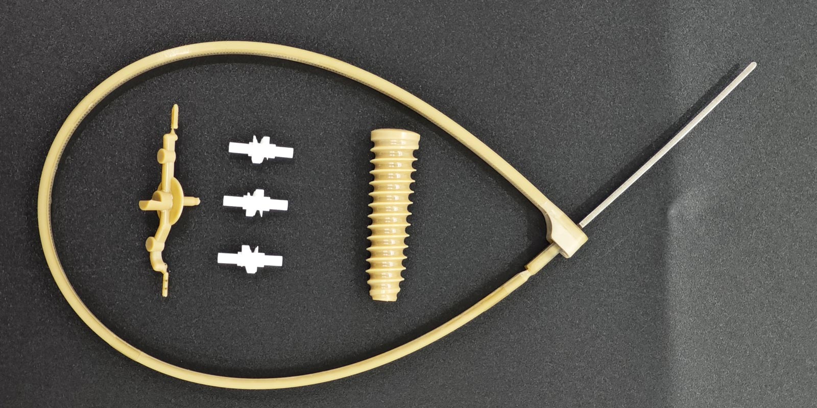
The precision requirements of medical molds far exceed those of ordinary molds, creating exhaust challenges:
Microstructure Exhaust Dilemmas: The runner diameter of a cardiac stent mold is only 0.8 mm, requiring exhaust slot depths of 0.01-0.015 mm (compared to 0.03-0.05 mm for ordinary molds). Minor deviations can cause blockages.
Multi-Cavity Mold Balancing Issues: In a 16-cavity infusion set connector mold, pressure loss differences in the runner system can reach 15%, causing some cavities to fill too quickly and trap gas.
Hot Runner Dead Zones: One company's statistics show that residual gas in hot runner systems accounts for 32% of gas mark defects. Particularly, 0.05 mm gaps in needle-valve hot nozzles can retain 0.003 cm³ of gas.
Innovative Design Cases:
Medical injection molding exhibits 3-5 times greater sensitivity to process parameters than ordinary products, requiring a "three-level control system":
Real-Time Monitoring Technologies:
As medical injection molding advances toward "micro-nano" (feature sizes <0.1 mm) and "multi-material" (e.g., PEEK + titanium alloy composites) applications, gas mark control faces greater challenges. Emerging technologies such as intelligent exhaust systems, nanoscale mold polishing, and supercritical fluid-assisted injection molding are gaining traction. One company has successfully developed "self-exhausting molds" that use micro-nano structures on core surfaces to enable autonomous gas migration, reducing gas mark rates in implants to below 0.03%. This indicates that the future of medical injection molding will enter a "zero gas mark" era, requiring deep integration and innovation across material science, mold technology, and process control.
PREV:Why Are Medical Injection-Molded Products Prone to Deformation? What Are the Preventive Measures?
Add: 62 Jinghai East Road, Chang'an Town, Dongguan City, Guangdong Province
Whatsapp: 13302615729
Tel: 86-133-0261-5729
Email: info@yizemould.com
Add: 62 Jinghai East Road, Chang'an Town, Dongguan City, Guangdong Province
Whatsapp: 13302615729
Tel: 86-133-0261-5729
Email: info@yizemould.com
 Home
Home