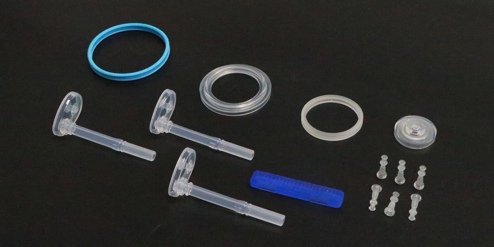
In the field of medical injection molding, thin-wall injection-molded parts are widely used in disposable medical devices and implant packaging due to their lightweight and miniaturized characteristics. However, the issue of incomplete filling in fine areas (such as micro-holes and thin-wall ribs) and corner regions (such as right-angle bends and concave structures) has become a critical bottleneck restricting product yield and performance. This article systematically analyzes the causes from three dimensions: material rheology, mold design, and process parameters, and proposes targeted solutions.
I. Limitations of Material Rheological Properties
1. Melt Viscosity and Shear Thinning Effect
Medical-grade plastics (such as PP, PE, and PPSU) exhibit non-Newtonian fluid characteristics in their molten state, with viscosity decreasing as the shear rate increases. In thin-wall regions, the accelerated melt flow rate leads to an increased shear rate, causing a decrease in viscosity. While this facilitates flow, excessive shear thinning can occur when the shear rate exceeds a critical value, resulting in premature solidification of the melt at the end of fine channels due to rapid kinetic energy decay. For example, during the injection molding of a 0.15 mm micro-hole in an insulin pen component, the melt temperature dropped by 15°C due to shear thinning, leading to cold plug formation.
2. Melt Fracture and Surface Slip
When the melt flows through micro-channels (diameter < 0.5 mm), high shear stress can induce melt fracture, manifesting as sharkskin patterns or complete fracture on the flow surface. Medical-grade PC material exhibits a 60% probability of melt fracture when flowing through a 0.3 mm channel at a shear rate exceeding 5000 s⁻¹, causing flow interruption. Additionally, insufficient adhesion between the melt and the mold cavity surface can lead to slip, particularly when using PTFE-coated molds, where slip velocity can reach three times that of conventional molds, exacerbating filling deficiencies.
II. Mold Design Defects
1. Imbalanced Runner System
Traditional runner designs often neglect pressure compensation for thin-wall regions. In the injection molding of a blood dialyzer end cap, the main runner diameter was 8 mm, while the runner diameter at the thin-wall rib was only 1.2 mm, resulting in a pressure loss ratio of 1:4.2. According to Darcy's law, pressure loss is proportional to runner length and inversely proportional to the fourth power of diameter, leaving the thin-wall region with less than 30% of the initial melt pressure, insufficient to overcome molding resistance.
2. Inadequate Gate Position and Quantity Optimization
Medical injection-molded parts are sensitive to residual stress, requiring gate design to balance filling and deformation control. For components with right-angle corners, a single-gate design causes the melt to flow in an "S" shape, creating weld lines and filling voids at the corners. Using multi-gate systems (such as needle-valve hot runners) can increase corner filling rates from 72% to 95%, but gate balancing is essential to avoid weld strength degradation due to melt front convergence time differences exceeding 0.05 s.
3. Venting System Failure
The rapid filling time (< 0.5 s) in thin-wall injection molding requires timely evacuation of cavity air to prevent backpressure from impeding melt flow. During the injection molding of medical-grade PPSU, air compression in the cavity can generate backpressure up to 15 MPa, equivalent to 40% of the injection pressure. In a surgical instrument handle molding case, adding 0.02 mm deep × 3 mm wide venting slots in corner regions increased filling rates from 81% to 98%.
III. Process Parameter Mismatch
1. Injection Speed and Pressure Curve Control
Thin-wall injection molding requires a "high-speed-high-pressure-holding pressure" three-stage control strategy. Initial high-speed injection (> 500 mm/s) reduces melt cooling time but must be synchronized with pressure increases. In the molding of an implant packaging box, increasing injection speed from 300 mm/s to 600 mm/s without raising holding pressure from 80 MPa to 120 MPa increased thin-wall shrinkage from 2.1% to 3.8%, forming sink marks.
2. Melt Temperature Gradient Management
Medical plastics are temperature-sensitive, with melt temperature fluctuations exceeding ±5°C significantly affecting flowability. Infrared temperature measurements revealed that during the molding of an infusion set drip chamber, as the screw head melt temperature dropped from 260°C to 250°C, thin-wall filling rates decreased linearly, with each 1°C drop reducing filling by 0.8%. Closed-loop temperature control systems are therefore essential to maintain temperature fluctuations within ±2°C.
3. Dynamic Mold Temperature Regulation
Thin-wall injection molding requires zonal mold temperature control. For components with micro-holes, the mold temperature in the hole wall region should be 5-8°C higher than the main body to delay melt solidification. Using an oil temperature machine and steam heating combination system increased the filling rate of micro-holes in a diagnostic reagent box from 65% to 92% while controlling warpage within 0.1 mm.
IV. Comprehensive Solutions
-
Material Modification: Adding 0.5-1.5% nano-silica enhances melt elasticity and reduces melt fracture; using low-molecular-weight branched polymers decreases shear viscosity.
-
Mold Optimization: Applying Moldflow simulation for runner balancing ensures melt front arrival time differences < 0.03 s between gates; 3D-printed conformal cooling channels improve mold temperature uniformity by 40%.
-
Process Innovation: Developing "vibration injection molding" technology, which applies 200-500 Hz micro-vibrations during holding pressure, increases melt filling depth by 15%; adopting supercritical fluid-assisted injection molding (SCF) with CO₂ as a physical blowing agent reduces melt viscosity by 30-50%.
Conclusion
The filling quality of medical thin-wall injection-molded parts results from the synergistic interaction of material, mold, and process factors. By deeply understanding melt flow fundamentals, optimizing mold structural design, and precisely controlling process parameters, the filling challenges in fine areas and corners can be systematically addressed. With the development of intelligent injection molding technologies, machine learning-based adaptive process parameter regulation systems will provide more efficient solutions for the medical injection molding industry.


 Home
Home
